The Node Voltage Method For Analysis Of Electric Circuits
Node voltage analysis is the most general method for the analysis of electric circuits. In this technical article, its application to linear resistive circuits is illustrated. The node voltage method is based on defining the voltage at each node as an independent variable. One of the nodes is selected as a reference node (usually-but not necessarily-ground), and each of the other node voltages is referenced to this node.
Once each node voltage is defined, Ohm’s law may be applied between any two adjacent nodes to determine the current flowing in each branch.
In the node voltage method, each branch current is expressed in terms of one or more node voltages; thus, currents do not explicitly enter into the equations.
Figure 1 // In the node voltage method, we assign the node voltages va and vb; the branch current flowing from a to b is then expressed in terms of these node voltages.

Figure 1 above illustrates how to define branch currents in this method. Once each branch current is defined in terms of the node voltages, Kirchhoff’s current law is applied at each node:
Figure 2 illustrates this procedure. By Kirchhoff’s current law (KCL): i1 – i2 – i3 = 0. In the node voltage method, we express KCL by:

The systematic application of this method to a circuit with n nodes leads to writing n linear equations. However, one of the node voltages is the reference voltage and is therefore already known, since it is usually assumed to be zero. Thus, we can write n − 1 independent linear equations in the n − 1 independent variables (the node voltages).
Node analysis provides the minimum number of equations required to solve the circuit, since any branch voltage or current may be determined from knowledge of node voltages.
The node analysis method may also be defined as a sequence of steps, as outlined in the following box:
Node Voltage Analysis Method //
- Select a reference node (usually ground). This node usually has most elements tied to it. All other nodes are referenced to this node.
- Define the remaining n−1 node voltages as the independent or dependent variables. Each of the m voltage sources in the circuit is associated with a dependent variable. If a node is not connected to a voltage source, then its voltage is treated as an independent variable.
- Apply KCL at each node labeled as an independent variable, expressing each current in terms of the adjacent node voltages.
- Solve the linear system of n−1−m unknowns.
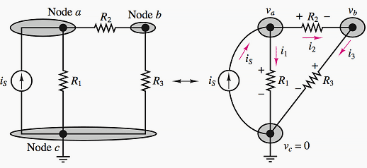
Following the above procedure outlined in the box guarantees that the correct solution to a given circuit will be found, provided that the nodes are properly identified and Kirchhoff’s current law (KCL) is applied consistently. As an illustration of the method, consider the circuit shown in Figure 3.

The circuit is shown in two different forms to illustrate equivalent graphical representations of the same circuit. The circuit on the right leaves no question where the nodes are. The direction of current flow is selected arbitrarily (assuming that is is a positive current).
Application of KCL at node a yields:
whereas at node b:
It is instructive to verify (at least the first time the method is applied) that it is not necessary to apply Kirchhoff’s current law (KCL) at the reference node.
The equation obtained at node c,
is not independent of previous two equations 1 and 2; in fact, it may be obtained by adding the equations obtained at nodes a and b. This observation confirms the statement made earlier:
In a circuit containing n nodes, we can write at most n − 1 independent equations. Now, in applying the node voltage method, the currents i1, i2, and i3 are expressed as functions of va, vb, and vc, the independent variables.
Ohm’s law requires that i1, for example, be given by:
since it is the potential difference va − vc across R1 that causes current i1 to flow from node a to node c. Similarly,

Substituting the expression for the three currents in the nodal equations (equations 1 and 2), we obtain the following relationships:

Equations above may be obtained directly from the circuit, with a little practice. Note that these equations may be solved for va and vb, assuming that is, R1, R2, and R3 are known. The same equations may be reformulated as follows:


No comments