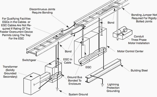
Practices for grounding and bonding of cable trays
Metallic Cable Trays
Cable tray may be used as the Equipment Grounding Conductor (EGC) in any installation where qualified persons will service the installed cable tray system. There is no restriction as to where the cable tray system is installed. The metal in cable trays may be used as the EGC as per the limitations of table 392.60(A).
All metallic cable trays shall be grounded as required in Article 250.96 regardless of whether or not the cable tray is being used as an equipment grounding conductor (EGC).
The EGC is the most important conductor in an electrical system as its function is electrical safety.

There are three wiring options for providing an EGC in a cable tray wiring system:
- An EGC conductor in or on the cable tray.
- Each multi-conductor cable with its individual EGC conductor.
- The cable tray itself is used as the EGC in qualifying facilities.
Correct bonding practices
To assure that the cable tray system is properly grounded
If an EGC cable is installed in or on a cable tray, it should be bonded to each or alternate cable tray sections via grounding clamps (this is not required by the NEC® but it is a desirable practice)
In addition to providing an electrical connection between the cable tray sections and the EGC, the grounding clamp mechanically anchors the EGC to the cable tray so that under fault current conditions the magnetic forces do not throw the EGC out of the cable tray.
A bare copper equipment grounding conductor should not be placed in an aluminum cable tray due to the potential for electrolytic corrosion of the aluminum cable tray in a moist environment.
For such installations, it is best to use an insulated conductor and to remove the insulation where bonding connections are made to the cable tray, raceways, equipment enclosures, etc. with tin or zinc plated connectors.
NEC Table 250.122 – Minimum size equipment grounding conductors for grounding raceway and equipment
Aluminum Cable Tray Systems
Table 392.60(A) – Metal area requirements for cable trays used as equipment grounding conductors
For Sl units: 1 square inch = 645
* Total cross-sectional area of both side rails for ladder or trough cable trays or the minimum cross-sectional area of metal in channel cable trays or cable trays of one-piece construction.
** Steel cable trays shall not be used as equipment grounding conductors for circuits with ground-fault protection above 600 amperes. Aluminum cable trays shall not be used as equipment grounding conductors for circuits with ground-fault protection above 2000 amperes.
Table 392.60(A) “Metal Area Requirements for Cable Trays used as Equipment Grounding Conductors” shows the minimum cross-sectional area of cable tray side rails (total of both side rails) required for the cable tray to be used as the Equipment Grounding Conductor (EGC) for a specific Fuse Rating, Circuit Breaker Ampere Trip Rating or Circuit Breaker Ground Fault Protective Relay Trip Setting.
These are the actual trip settings for the circuit breakers and not the maximum permissible trip settings which in many cases are the same as the circuit breaker frame size.
If the maximum ampere rating of the cable tray is not sufficient for the protective device to be used, the cable tray cannot be used as the EGC and a separate EGC must be included within each cable assembly or a separate EGC has to be installed in or attached to the cable tray.
For specific areas requiring bonding for electrical continuity, refer to Figures 1-4.
Non-metallic cable trays do not serve as a conductor. It is also recommended that wire mesh cable trays not be used as an equipment grounding conductor.
Although permitted by the NEC, it is recommended due to the unique nature of the wire mesh, fittings are manufactured in the field from straight sections by cutting away the current carrying structural wires, reducing the current-carrying capability of the system. As such, the use of wire mesh cable trays as an equipment grounding conductor is not recommended.
If the wire mesh cable tray is to be used as an equipment grounding conductor, then the installation of a ground wire is recommended.
If a wire mesh cable tray is supporting cable with a built-in equipment grounding conductor or control or signal cables, then the tray should have a low impedance path to a non-system ground to reduce noise and remove induced or stray currents. A separate grounding cable attached to the wire mesh cable tray is not usually required.
References:
- CABLE TRAY MANUAL Based on the 2011 National Electrical Code – EATON
- Cable Tray Installation Guidelines – NEMA Standards Publication VE 2-2006


No comments