First, let’s say some words about basics of the reactive power in system. Reactive current arises in every electrical system. Not only large loads, but smaller loads as well require reactive power. Generators and motors produce reactive power, which causes unnecessary burdens to and power losses in the lines.
Figure 1 shows the block diagram for the network loading.
Figure 1 – Equivalent circuit diagram of a network with different loading: a) Equivalent circuit; b) Phasor diagram
Reactive power is necessary to generate magnetic fields, e.g. in motors, transformers and generators. This power oscillates between the source and the load and represents an additional loading.
Example 1 – Determination of Capacitive Power
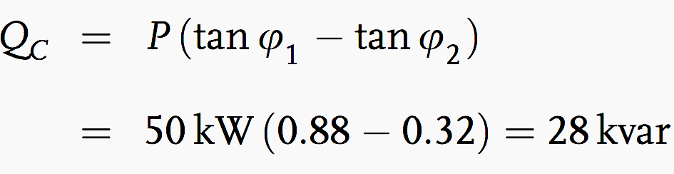
A load has an effective power of P = 50 kW at 400 V and the power factor is to be compensated from cosφ = 0.75 to cosφ = 0.95. Determine the required capacitive power. The power and current before compensation are:
The power and current after compensation are:
The required capacitive power is:
Example 2 – Capacitive Power With k Factor
The capacitive power can be determined with the factor k for a given effective power. The k factor is read from a table 1 – Multipliers to determine capacitor kilovars required for power factor correction (see below) and multiplied by the effective power. The result is the required capacitive power.
For an increase in the power factor from cosφ = 0.75 to cosφ = 0.95, from the table 1 we find a factor k = 0.55:
Example 3 – Determination of Cable Cross-Section
A three-phase power of 250 kW, with Un = 400 V, at 50 Hz is to be transmitted over a cable 80 m in length. The voltage drop must not exceed 4% =16 V. The power factor is to be increased from cosφ = 0.7 to cosφ = 0.95. What is the required cable cross-section?
The current consumption before compensation is:
The current consumption after compensation is:
The effective resistance per unit length for 516 A is:
According to Table 2 (see below) we must choose a cable with a cross-section of 4 × 95 mm2. The effective resistance per unit length for 380 A is:
Here, a cable cross-section of 4 × 70 mm2 is required. As this example illustrates, the improved power factor leads to lower costs because of the reduced cross-section.
Example 4 – Calculation of the c/k Value
Given a 150 condenser battery, i.e. 5 stages of 30 each, a supply voltage of 400 V, and an instrument transformer with a k of 500 A/5 A, how large is the c/k value? The ratio c/k is given by.
Tables
Table 1 – Multipliers to Determine Capacitor Kilovars Required for Power Factor Correction
Table 1 – Multipliers to Determine Capacitor Kilovars Required for Power Factor Correction
Table 2 – Resistance per unit length for (Cu) cable with plastic insulation
Table 2 – Resistance per unit length for (Cu) cable with plastic insulation
Power supply companies and the consumers of this electrical energy are interested in reducing these disadvantages as well as possible. On the other hand, non-linear loads and phase-controlled inverters cause harmonics, which lead to voltage changes and a decrease in the power factor. In order to reduce these harmonics, series resonant (filter) circuits are used.Now, let’s take few examples to calculate the following:
Example 1 – Determination of Capacitive Power
A load has an effective power of P = 50 kW at 400 V and the power factor is to be compensated from cosφ = 0.75 to cosφ = 0.95. Determine the required capacitive power. The power and current before compensation are:
The power and current after compensation are:
The required capacitive power is:
4 example calculations of compensation for reactive power
Reviewed by genie-electronique
on
10:44:00 AM
Rating: 5


No comments